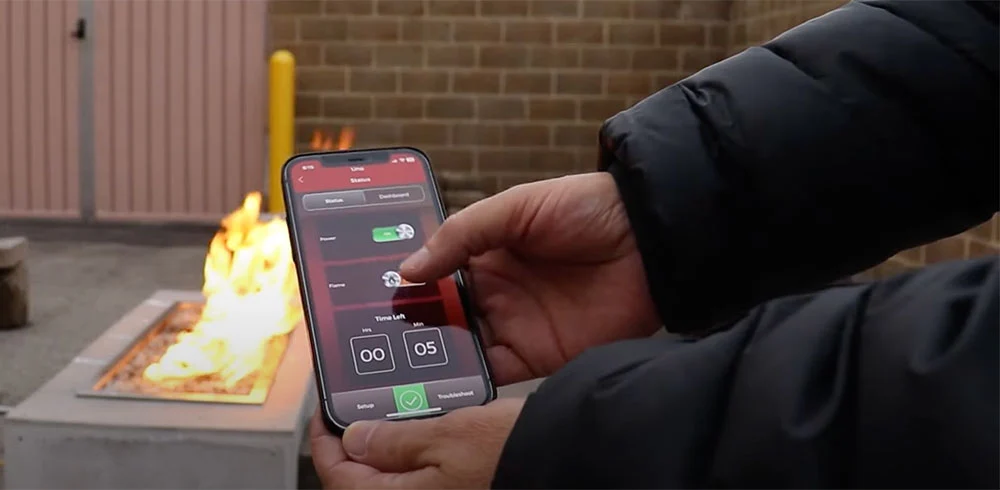
Electronic fire pit ignition systems provide convenient control, flame monitoring and integration options for residential and commercial outdoor projects. However, reliable operation depends on more than the ignition components themselves. Fuel supply, electrical service, ventilation, drainage, fire media placement, component compatibility and installation conditions all affect how the system performs.
For contractors, understanding the complete ignition sequence can make it easier to specify the right system, coordinate the required trades, commission the installation and diagnose future service issues. This SpotixPro guide explains how electronic fire pit ignition systems work, what to consider during project planning and how to approach common performance problems systematically.
Always follow the installation, operation and service instructions provided by the manufacturer for the specific burner and ignition system. Gas supply changes, pressure testing, electrical work and internal component repairs should be completed by qualified professionals in accordance with applicable codes.
What Contractors Should Know About Electronic Fire Pit Ignition Systems
An electronic ignition system automates the lighting process and monitors whether the fire pit has established a flame. Depending on the system, users may control the fire feature through a wall switch, timer, remote, automation system or mobile application.
Electronic ignition systems are often selected for:
- Custom residential fire features
- Commercial patios and hospitality projects
- Pool decks and outdoor kitchens
- Multifamily developments
- Automated outdoor living spaces
- Fire features with remote or app control
- Installations requiring flame-sensing safety technology
- Projects where manual lighting is impractical
Although electronic ignition offers convenience, it also introduces electrical components, control modules, sensors and communication devices that must be properly selected and protected.
Electronic Ignition Compared With Other Fire Pit Ignition Options
The appropriate ignition system depends on the project requirements, expected level of control, budget, installation environment and customer expectations.
Match-Light Ignition
Match-light systems use a manually operated gas valve and an external flame source. They are mechanically simple and do not require electrical service, but they require the user to approach the burner during startup.
Match-light ignition may be appropriate when:
- The project requires a simple manual system.
- Electrical power is not available near the fire feature.
- Remote operation is not needed.
- The appliance and local requirements permit match-light operation.
Push-Button Spark Ignition
Push-button systems use a battery-powered or piezo igniter to create a spark near the burner. The user generally opens the gas valve manually and presses the ignition button.
These systems provide easier startup than match-light models while remaining relatively simple.
Electronic Ignition
Electronic ignition systems automatically control the ignition sequence. A control module activates the igniter, releases gas to the pilot, verifies the pilot flame and then opens the main burner valve.
Depending on the model, electronic ignition may support:
- Wall-switch control
- Timer control
- Remote control
- Bluetooth or app connectivity
- Smart-home or automation integration
- Automatic relight attempts
- Flame monitoring
- ON/OFF operation
- HI/LO flame adjustment
How an Electronic Fire Pit Ignition System Works
Understanding the normal ignition sequence helps contractors identify which part of the system is failing when a fire pit will not light or remain operating.
- The user activates the fire pit through a switch, timer, remote, app or automation system.
- The command is sent to the ignition control module.
- The control module confirms that the system is ready to begin the ignition sequence.
- Power is supplied to the igniter or pilot ignition component.
- The pilot gas valve opens.
- The pilot gas ignites.
- A thermocouple, flame rod or other sensing component verifies the pilot flame.
- The control module opens the main gas valve.
- The pilot flame ignites the gas flowing from the main burner.
- The system continues monitoring the flame while the fire pit operates.
- If flame verification is lost, the system may attempt to relight or enter a safety lockout.
When diagnosing a problem, contractors should identify the exact point where this sequence stops.
Choosing the Right Electronic Ignition System
The ignition system should be selected early in the project so the gas, electrical, enclosure and control requirements can be coordinated before construction begins.
Confirm the Fuel Type
Natural gas and propane systems use different orifices, regulators and combustion components. Confirm the fuel source before ordering the burner or ignition system.
Do not assume an ignition system can be converted in the field unless the manufacturer provides a listed conversion procedure and approved components.
Determine the Required Level of Control
Ask how the customer expects to operate the fire feature.
Possible control methods include:
- Basic ON/OFF switch
- Countdown timer
- Handheld remote
- Bluetooth application
- HI/LO flame adjustment
- Home automation relay
- Commercial building controls
- Emergency shutoff controls
The selected ignition model must be compatible with the desired control method.
Consider Residential Versus Commercial Use
Commercial installations may experience longer operating periods, more frequent cycling and greater exposure to customer misuse. They may also require additional controls, access restrictions or emergency shutoff provisions.
For commercial projects, review:
- Expected daily runtime
- Operating responsibility
- Control access
- Local code requirements
- Required safety shutoffs
- Service accessibility
- Maintenance scheduling
- Warranty terms for commercial use
Review Environmental Exposure
Outdoor ignition components may be exposed to rain, snow, irrigation, humidity, debris, insects and temperature changes. Select a system approved for the intended outdoor environment and follow all manufacturer requirements for drainage, ventilation and weather protection.
Planning an Electronic Ignition Installation
Many ignition-related callbacks begin during project planning. Coordinating the gas, electrical, masonry, drainage and control requirements before construction can prevent difficult corrections after the enclosure is complete.
Gas Supply Requirements
Verify that the fuel system can support the full rated input of the burner under operating conditions.
Gas system planning should account for:
- Burner BTU rating
- Total developed gas-line length
- Gas type
- Available supply pressure
- Pipe material
- Fittings, valves and restrictions
- Regulator capacity
- Gas meter or propane supply capacity
- Other appliances operating simultaneously
Electronic ignition cannot compensate for an undersized gas supply. Low operating pressure may cause pilot failure, delayed ignition, flame loss or repeated system lockout.
Electrical Requirements
Confirm the required voltage, transformer, wiring method and control configuration before installation.
Review:
- Input voltage
- Transformer location
- Low-voltage or line-voltage wiring requirements
- Dedicated circuit requirements
- Grounding and polarity
- Weather-resistant connections
- Disconnecting means
- Control wire routing
- Maximum wire lengths
- Automation interface requirements
Incorrect voltage, poor grounding or improper wire routing can prevent ignition or create intermittent operation.
Component Compatibility
The burner, valve, pilot assembly, control module, transformer, remote receiver and other controls must be designed to operate together.
Avoid combining components from different systems unless the manufacturer specifically approves the configuration.
Before installation, verify:
- Burner and ignition compatibility
- Fuel configuration
- Valve capacity
- Control module compatibility
- Transformer specifications
- Remote or app compatibility
- Required communication components
- Approved replacement parts
Valve Box Placement and Service Access
Electronic ignition systems require future access for diagnosis, cleaning and component replacement. The valve box and control components should not be permanently sealed behind masonry or installed where they cannot be reached without demolition.
Plan access for:
- Valve box
- Control module
- Transformer
- Gas shutoff
- Electrical connections
- Remote receiver or communication module
- Pilot assembly
- Burner connections
Service access should remain usable after the finish materials, fire media and surrounding landscaping are installed.
Enclosure Ventilation
Custom enclosures must provide the ventilation required by the ignition-system manufacturer. Ventilation helps manage heat and may prevent unburned gas from accumulating inside the enclosure.
Ventilation requirements may depend on:
- Fuel type
- Burner input
- Enclosure volume
- Valve-box location
- Control-module placement
- Manufacturer specifications
Propane is heavier than air, which makes properly positioned lower ventilation openings especially important where required.
Drainage and Moisture Management
Water is a common cause of electronic ignition failure. Rain, snow, irrigation and condensation can collect beneath the burner or inside the valve enclosure.
The installation should provide:
- Drainage through the burner pan
- A path for water to exit the enclosure
- Protection for control modules and electrical connections
- Proper surface grading
- Clear drain openings
- Appropriate use of a compatible cover
A cover can reduce weather exposure, but it should not be treated as a replacement for proper drainage.
Fire Media Requirements
Fire glass, lava rock and other media must be installed at the approved depth and kept clear of ignition components.
Improper media placement can:
- Bury the pilot assembly
- Block the igniter
- Reduce pilot flame contact with the sensor
- Delay flame travel to the main burner
- Obstruct burner ports
- Trap excessive heat
- Contribute to soot
Install fire glass and other media according to the burner and ignition-system instructions.
Common Electronic Ignition Installation Mistakes
Many ignition failures are related to installation conditions rather than defective components.
Common mistakes include:
- Ordering the wrong fuel configuration
- Using an undersized gas line
- Failing to account for simultaneous appliance demand
- Using an incorrect regulator
- Supplying the wrong voltage
- Failing to provide proper grounding
- Installing incompatible controls
- Routing wiring against hot surfaces
- Placing the transformer in an unapproved location
- Installing the valve box without service access
- Providing insufficient enclosure ventilation
- Failing to provide drainage
- Allowing water to collect around the control module
- Burying the pilot assembly in fire media
- Blocking burner ports with media
- Installing unapproved media
- Failing to test the system before completing masonry
- Not documenting model and serial information
Electronic Fire Pit Ignition Commissioning Checklist
Commissioning should be completed before the project is handed over to the customer. Testing the complete system can reveal installation issues while the required trades are still available.
- Confirm the burner and ignition system match the specified fuel type.
- Verify the gas line is sized for the full burner input.
- Confirm regulator type, pressure and capacity.
- Leak-test all gas connections using approved procedures.
- Verify inlet and operating pressure according to the manufacturer.
- Test the fire pit while other major gas appliances are operating when appropriate.
- Confirm the correct electrical voltage.
- Verify polarity and grounding.
- Inspect all wiring and connections.
- Confirm the transformer and controls are installed in approved locations.
- Verify enclosure ventilation.
- Confirm the burner pan and enclosure drain freely.
- Inspect the pilot, igniter and flame sensor.
- Arrange fire media according to the manufacturer's requirements.
- Cycle the ignition system multiple times.
- Confirm the pilot ignites consistently.
- Confirm the flame-sensing system verifies the pilot.
- Inspect the main burner ignition pattern.
- Confirm the flame remains stable after ignition.
- Test shutoff and safety functions.
- Pair remotes, apps and communication modules.
- Test wall switches, timers and automation controls.
- Check for error codes or diagnostic indicators.
- Observe operation under normal site conditions.
- Photograph the completed installation.
- Record model, serial and commissioning information.
- Review system operation with the customer.
Contractor Diagnostic Workflow
A consistent diagnostic sequence helps contractors isolate the cause of an ignition problem without replacing parts unnecessarily.
- Confirm the customer's complaint.
- Determine whether the system ever operated correctly.
- Identify the ignition manufacturer and model.
- Review the installation manual and wiring diagram.
- Document any error codes or LED flash patterns.
- Shut off gas and power before visual inspection.
- Inspect the installation for water, debris and damaged wiring.
- Verify electrical power, polarity and grounding.
- Confirm fuel supply and operating pressure.
- Activate the system and observe the ignition sequence.
- Identify the exact point where the sequence stops.
- Inspect the corresponding component or system area.
- Complete the required corrective work.
- Restart and cycle the system repeatedly.
- Document the findings and customer handoff.
Pre-Service Questions for the Customer
Before arriving at the project site, ask questions that help narrow the diagnostic path.
- Did the fire pit ever operate correctly?
- When did the problem begin?
- Is the issue constant or intermittent?
- Does the igniter glow or spark?
- Does the pilot ignite?
- Does the main burner ignite?
- How long does the fire pit operate before shutting down?
- Does an error code or LED flash pattern appear?
- Does the issue happen after rain or irrigation?
- Does it happen only during windy or cold conditions?
- Does performance change when other gas appliances operate?
- Has fire media recently been added or rearranged?
- Has the remote, app, transformer or control wiring been changed?
- Has anyone attempted to repair or reset the system?
Electronic Ignition Troubleshooting Chart for Contractors
| Reported Problem | System Area to Inspect | Diagnostic Checks | Common Installation Cause |
|---|---|---|---|
| No Power or Response | Power supply, transformer, wiring and controls | Verify breaker, switch, transformer output, voltage, polarity, fuse, ground and visible wiring connections. | Incorrect voltage, failed transformer, open fuse, loose connection, poor grounding or damaged wiring |
| Igniter Does Not Glow or Spark | Igniter, wiring and control module | Confirm the system has entered the ignition sequence. Inspect igniter wiring, connections, resistance or continuity where specified and module output according to the manufacturer. | Damaged igniter, incorrect wiring, moisture exposure, failed control module or incompatible component |
| Igniter Activates but Pilot Does Not Light | Pilot gas supply, igniter position and pilot assembly | Verify pilot gas flow, fuel pressure, igniter alignment and pilot-orifice condition. Inspect for air in a new gas line, water, debris or insects. | Closed gas valve, low pressure, clogged pilot, incorrect igniter placement or wrong fuel configuration |
| Pilot Lights but Main Burner Does Not Ignite | Flame sensor, thermocouple, main valve and burner | Confirm the pilot flame properly contacts the sensor. Inspect sensor connections, main valve operation, burner obstruction and fire media placement. | Weak pilot flame, misaligned sensor, buried pilot, blocked burner, failed valve or low operating pressure |
| Main Burner Ignites Slowly | Burner ports, pilot location and media | Inspect flame travel from the pilot to the main burner. Confirm burner ports are open and media is not obstructing the ignition path. | Excessive media, blocked burner ports, incorrect pilot position or inadequate gas pressure |
| System Shuts Down After Ignition | Flame sensing, operating pressure and wind exposure | Observe whether the sensor remains in the pilot flame. Test pressure under load and inspect for wind moving the flame away from the sensor. | Low pressure, poor sensor alignment, unstable pilot flame, improper media or excessive wind |
| System Cycles On and Off | Flame sensor, power supply, gas supply and controls | Monitor the pilot, operating pressure, voltage and control signal throughout the cycle. Check for loose wiring and intermittent communication. | Unstable gas supply, loose connection, overheating, flame-sensing interruption or automation issue |
| System Enters Lockout | Ignition sequence and control module | Record the error code before resetting. Determine whether the system failed during ignition, flame verification, communication or operation. | Repeated ignition failure, flame loss, sensor issue, communication failure or internal control fault |
| Over-Temperature Error | Enclosure ventilation and component placement | Inspect enclosure openings, control-module location, nearby heat sources and fire media depth. Measure conditions according to manufacturer procedures where required. | Insufficient ventilation, buried components, excessive media or controls mounted too close to heat |
| Remote or App Does Not Respond | Communication module, pairing and power | Confirm module power, batteries, pairing status, communication cable, range and required app settings. | Unpaired device, failed transceiver, poor module location, damaged cable or incompatible control |
| Failure After Rain or Irrigation | Drainage, valve box and electrical components | Inspect for standing water, corrosion, wet wiring, blocked drains and moisture inside the valve box or control enclosure. | Poor drainage, unprotected components, surface runoff or irrigation directed toward the fire feature |
| Performance Drops When Other Gas Appliances Operate | Total gas system capacity | Test the fire pit under simultaneous appliance demand. Review meter, regulator, manifold and branch-line sizing. | Gas system sized for individual demand instead of total connected load |
How to Use Electronic Ignition Error Codes
Error codes help identify the stage of operation in which the ignition system detected a problem. Depending on the manufacturer and model, fault information may appear through:
- LED flash patterns on the control module
- Remote-control indicators
- Mobile-app error logs
- Controller displays
- Automation-system feedback
Before resetting the system, record:
- The exact code or flash count
- When the code appeared
- Whether the pilot ignited
- Whether the main burner ignited
- How long the system operated
- Weather and site conditions
- Any recent changes to the system
Do not assume that an error-code description automatically identifies the failed part. For example, an igniter-related fault could be caused by the igniter, wiring, power supply, control module or an installation condition that prevented the ignition sequence from completing.
Always compare the code with the troubleshooting chart for the exact ignition model.
Diagnosing Power and Electrical Problems
If the system does not respond, begin with the electrical supply rather than the gas components.
Verify:
- The breaker is on.
- The required wall switch or disconnect is on.
- The transformer has input power.
- The transformer is producing the required output voltage.
- The control module is receiving power.
- Fuses are intact.
- Polarity is correct.
- The system is properly grounded.
- Connections are secure.
- Wiring insulation is not damaged.
- Communication cables are connected correctly.
- Moisture has not entered electrical enclosures.
Intermittent power problems may only appear after components heat up, when moisture is present or when a loose connection is disturbed.
Diagnosing Pilot and Igniter Problems
If the system receives power and begins the ignition sequence, observe the igniter and pilot assembly.
Igniter Does Not Activate
Potential causes include:
- Failed igniter
- Damaged wiring
- Loose connection
- Incorrect module output
- Blown fuse
- Control-module failure
- Moisture damage
- Incorrect replacement component
Igniter Activates but Pilot Does Not Light
Inspect for:
- Air in a new gas line
- Closed upstream valve
- Low gas pressure
- Clogged pilot orifice
- Debris or insect activity
- Water inside the pilot assembly
- Incorrect igniter position
- Wrong fuel components
- Damaged pilot tubing
Cleaning or disassembling pilot components should be completed only as permitted by the manufacturer and by a qualified service professional.
Diagnosing Flame-Sensing Problems
After the pilot ignites, the system must verify the flame before opening the main gas valve. If flame verification fails, the system may shut down or attempt another ignition cycle.
Inspect whether:
- The pilot flame is large and stable enough.
- The pilot flame properly contacts the thermocouple or sensor.
- The sensing component is clean.
- The sensing component is positioned correctly.
- The electrical connection is secure.
- Fire media is interfering with the pilot flame.
- Wind is moving the flame away from the sensor.
- Operating pressure remains stable.
- The sensor is compatible with the control module.
A sensor should not be replaced until the pilot flame, gas supply, media placement and wiring have been evaluated.
Diagnosing Main Burner Ignition Problems
If the pilot is verified but the main burner does not ignite, the problem may be related to the main valve, burner, fuel supply or flame path.
Check:
- Whether the control module is commanding the main valve to open
- Main valve wiring and connections
- Gas pressure during the ignition sequence
- Burner-port obstruction
- Water or debris inside the burner
- Fire media blocking flame travel
- Correct burner orientation
- Burner and valve compatibility
- Correct fuel configuration
A damaged or heavily corroded gas fire pit burner may require replacement, but installation and fuel-supply issues should be ruled out first.
Environmental Conditions That Affect Electronic Ignition
Outdoor systems can fail intermittently because of conditions that are not present during a service visit.
Evaluate:
- Prevailing wind
- Crosswinds through enclosure vents
- Heavy rain
- Snow and ice
- Freezing temperatures
- Standing water
- Irrigation overspray
- High humidity
- Salt air
- Leaves and landscaping debris
- Spider webs and insects
- Rodent damage
- Direct heat exposure
- Movement or settling of the enclosure
Wind
Wind can prevent pilot ignition, move the pilot flame away from the sensor or disrupt flame travel to the main burner. Wind-related failures may occur only from a specific direction.
Water
Standing water can damage igniters, sensors, wiring, valves and control modules. A system that fails after rainfall should be inspected for blocked drains and improper enclosure design.
Insects and Debris
Small pilot orifices and burner openings may be obstructed by insects, spider webs, dirt or plant material. Seasonal inspection is especially important in systems that remain unused for long periods.
Temperature
Cold weather can affect propane vaporization and battery performance. Excessive enclosure heat can cause electronic modules to shut down or display over-temperature faults.
Preventative Maintenance Schedule
A routine maintenance plan can reduce ignition failures and extend component life. Always follow the maintenance schedule provided by the manufacturer.
Before Regular Use
- Inspect the burner area for debris.
- Confirm the enclosure is dry.
- Check fire media placement.
- Verify the pilot and ignition area are not buried.
- Confirm ventilation openings are clear.
Monthly During the Operating Season
- Inspect the flame pattern.
- Check for delayed ignition.
- Verify reliable startup and shutdown.
- Inspect the remote or control device.
- Clear leaves and debris.
- Confirm drainage openings remain clear.
Seasonally
- Remove and clean fire media as permitted.
- Inspect burner ports.
- Inspect pilot and sensing components.
- Check wiring for visible damage.
- Inspect the valve box for moisture or corrosion.
- Replace remote batteries where applicable.
- Test all control methods.
Annually
- Complete a professional system inspection.
- Verify gas pressure as required.
- Inspect valves and gas connections.
- Review electrical supply and grounding.
- Inspect ventilation and drainage.
- Test the ignition sequence repeatedly.
- Update installation and service records.
When Electronic Ignition Components May Need Replacement
Replacement should follow diagnosis rather than guesswork. Installing a new component will not correct an underlying gas, electrical, ventilation or drainage problem.
Replacement may be appropriate when a component is:
- Physically damaged
- Heavily corroded
- Water damaged
- Electrically open or failed according to approved testing
- No longer communicating with the system
- Outside manufacturer specifications
- Incompatible with the installed ignition model
- Confirmed defective through the manufacturer's diagnostic procedure
Before ordering parts, document the complete model number, serial number, fuel type, control functionality and existing component information.
What to Gather Before Contacting Technical Support
Manufacturer and supplier support teams can provide more useful guidance when contractors have detailed installation information available.
Gather:
- Ignition-system manufacturer
- Complete model number
- Serial number
- Fuel type
- Burner size and BTU rating
- ON/OFF or HI/LO configuration
- Gas line size and estimated length
- Regulator specifications
- Static and operating pressure information where available
- Input and output voltage information
- Transformer model
- Control method
- Error codes or LED flash patterns
- Description of the ignition sequence
- Point at which the sequence fails
- Photos of the pilot and burner
- Photos of the valve box and wiring
- Photos of enclosure ventilation
- Photos of drainage provisions
- Environmental conditions present during the failure
- Diagnostic steps already completed
Documenting the Installation and Service Work
Complete documentation supports future service, warranty inquiries and communication between trades.
Record:
- Manufacturer, model and serial number
- Fuel type
- Burner input
- Gas line size and length
- Regulator type and capacity
- Ignition-system type
- Control method
- Transformer and electrical specifications
- Fire media type and quantity
- Ventilation configuration
- Drainage configuration
- Commissioning results
- Error codes
- Replacement parts
- Service procedures completed
- Photos before and after service
For app-connected or software-controlled systems, also record the app version, device type and relevant connectivity information when available.
Customer Handoff and Callback Prevention
A thorough customer handoff can prevent service calls caused by improper operation or maintenance.
Review:
- Normal ignition sequence
- Expected startup time
- Correct shutdown procedure
- Location of the gas shutoff
- Wall-switch, timer, remote or app operation
- Remote battery replacement
- App pairing and account access
- Normal flame appearance
- Fire media placement restrictions
- Wind limitations
- Use of a compatible cover
- Drainage and moisture precautions
- Seasonal cleaning
- Winter shutdown procedures where applicable
- Error-code reporting
- Conditions that require professional service
Provide the customer with the installation and operation manual and retain a copy of the final project documentation.
Electronic Fire Pit Ignition FAQs
How does an electronic fire pit ignition system work?
An electronic ignition system activates an igniter, releases gas to a pilot, verifies the pilot flame and then opens the main burner valve. The system continues monitoring the flame and may shut off the gas if flame verification is lost.
What causes an electronic fire pit ignition to fail?
Potential causes include inadequate gas supply, low operating pressure, electrical failure, damaged wiring, poor grounding, pilot obstruction, flame-sensing problems, improper media placement, water intrusion, insufficient ventilation or failed components.
Why does the igniter activate but the pilot not light?
The pilot may not light because gas is not reaching the pilot, air remains in a new gas line, the pilot orifice is obstructed, the igniter is misaligned, pressure is insufficient or the system contains incorrect fuel components.
Why does the pilot light but the main burner not ignite?
The system may not be verifying the pilot flame, the main valve may not be opening, the burner may be obstructed or fire media may be interfering with flame travel. Gas pressure and component compatibility should also be checked.
What causes ignition lockout?
Ignition lockout generally occurs when the system cannot ignite or verify the flame within its programmed sequence. Causes may include low gas pressure, igniter failure, pilot obstruction, flame-sensing issues, communication problems or an internal control fault.
Can fire media cause electronic ignition problems?
Yes. Excessive or improperly placed fire media can bury the pilot, block the igniter, obstruct burner ports, interfere with the flame sensor and delay ignition of the main burner.
Can water damage an electronic ignition system?
Yes. Standing water and repeated moisture exposure can damage igniters, sensors, wiring, control modules, valves and communication components. Proper burner-pan and enclosure drainage are essential.
Why does an electronic ignition system overheat?
Overheating may result from insufficient enclosure ventilation, excessive fire media, improper control-module placement or heat from nearby components. Follow the manufacturer's ventilation and clearance requirements.
Should a contractor replace the ignition module first?
No. The contractor should identify the point where the ignition sequence fails and evaluate the gas supply, electrical service, wiring, pilot, flame sensor and installation conditions before replacing the control module.
How should contractors diagnose intermittent ignition problems?
Document when the issue occurs and evaluate changing conditions such as wind, rain, temperature, simultaneous gas demand, component heat, loose connections and communication range. Intermittent issues may not appear during a short service visit.
How can contractors reduce electronic ignition callbacks?
Callbacks can be reduced through proper system selection, compatible components, correct gas and electrical planning, adequate ventilation and drainage, careful media placement, complete commissioning, documentation and customer education.
Build More Reliable Electronic Fire Pit Systems
Electronic fire pit ignition systems offer convenient control and valuable flame-monitoring features, but their performance depends on the entire installation. Gas delivery, electrical service, ignition components, ventilation, drainage, media placement and environmental exposure must all be considered together.
By planning these requirements early, observing the complete ignition sequence and commissioning every system before customer handoff, contractors can diagnose problems more accurately and reduce unnecessary callbacks.
SpotixPro supports contractors, builders, designers and other trade professionals with exclusive trade pricing, dedicated account support and priority order processing. Our product specialists can also help identify compatible burners, ignition systems, controls and replacement components for upcoming installations and service projects.
The recommended title remains **SpotixPro Guide to Electronic Fire Pit Ignition Systems: Installation, Diagnostics & Commissioning**.